Have you ever wondered how modern electronics achieve precise, programmable control without the mechanical wear and reliability issues of traditional potentiometers? The answer lies in digital potentiometers – sophisticated integrated circuits that revolutionize how we approach variable resistance in electronic designs. In this comprehensive Microchip Digital Potentiometers: Features, Applications, and Selection Guide, I’ll walk you through everything you need to know about these remarkable components that are transforming electronics from audio equipment to industrial automation.
Digital potentiometers, or “digipots” as they’re commonly called, represent a quantum leap forward from their mechanical predecessors. Unlike traditional potentiometers that rely on physical wiper movement across a resistive track, digital potentiometers use electronic switching to achieve variable resistance with unprecedented precision and reliability.
Key Takeaways
- Microchip’s digital potentiometers offer resistance values from 5kΩ to 100kΩ with both volatile and non-volatile memory options
- Interface flexibility includes SPI (up to 10MHz) and I2C protocols supporting various speed modes for different applications
- Wide operating range from 1.8V to 5.5V with ultra-low power consumption under 1µA in shutdown mode
- High precision with 8-bit to 10-bit resolution providing 256 to 1024 discrete resistance positions
- Robust reliability featuring up to 1,000,000 wiper movement cycles and 100,000 EEPROM write cycles
Understanding Digital Potentiometer Fundamentals
What Makes Digital Potentiometers Special? 🔧
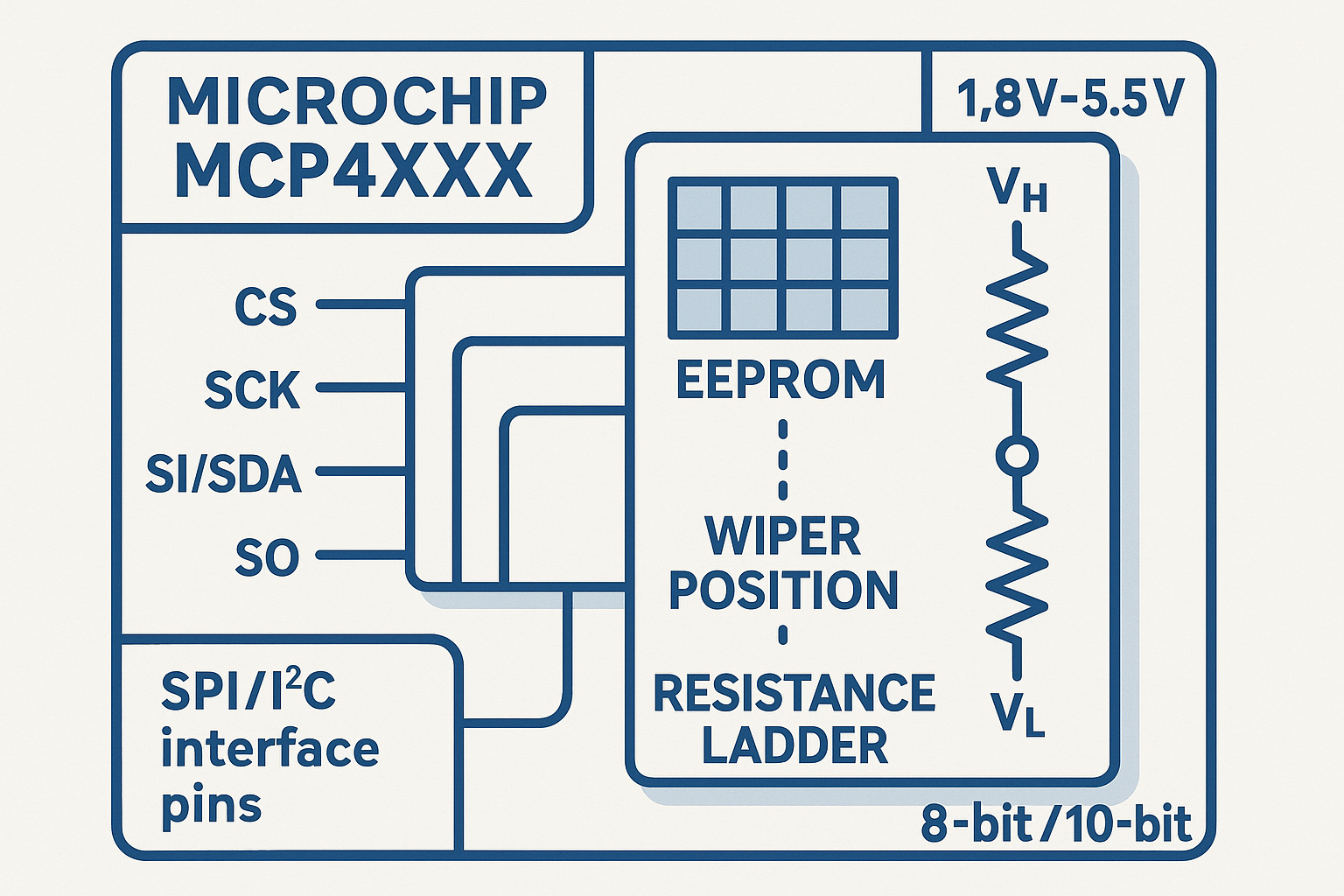
Digital potentiometers fundamentally change how we think about variable resistance. Instead of a mechanical wiper sliding across a resistive element, these devices use an array of resistors connected through electronic switches. When you send a digital command via SPI or I2C interface, the internal logic selects which resistors to include in the circuit path, effectively “moving” the wiper position electronically.
The beauty of this approach lies in its elimination of mechanical wear. Traditional potentiometers suffer from contact oxidation, dust accumulation, and physical degradation that leads to scratchy audio or inconsistent readings. Digital potentiometers sidestep these issues entirely, offering consistent performance throughout their operational lifetime.
Key Architecture Components
Microchip’s digital potentiometers contain several critical components:
- Resistor ladder network: Provides the actual resistance values
- Digital switches: Control which resistors are active in the circuit
- Memory storage: Either volatile SRAM or non-volatile EEPROM
- Interface logic: Handles SPI or I2C communication protocols
- Control registers: Store wiper position and configuration data
Understanding how potentiometers work and where to use them provides essential background for appreciating the advantages digital versions offer.
Comprehensive Features of Microchip Digital Potentiometers
Memory Technologies: Volatile vs Non-Volatile
Volatile SRAM-Based Models (MCP4561/2/3/4 Series)
Volatile digital potentiometers use SRAM to store wiper positions, which means they lose their settings when power is removed. However, this apparent limitation becomes an advantage in applications requiring:
- Frequent adjustments without wear concerns
- Fast switching between resistance values
- Lower cost for high-volume applications
- Security through automatic reset on power cycling
These models typically offer up to 1,000,000 wiper movement cycles, making them ideal for applications like real-time audio processing or dynamic gain control.
Non-Volatile EEPROM Models (MCP4551/2/3/4 Series)
EEPROM-based digital potentiometers retain their wiper positions even when power is removed. Key advantages include:
- Automatic restoration of settings on power-up
- Calibration storage for precision instruments
- Set-point memory for industrial applications
- Write protection features to prevent accidental changes
With 100,000 minimum EEPROM write cycles and 1,000,000 data retention years, these devices excel in applications requiring long-term stability and configuration persistence.
Interface Protocols and Communication Speed
SPI Interface Capabilities
Microchip’s SPI-based digital potentiometers operate at speeds up to 10MHz, making them suitable for high-speed applications. The SPI interface offers:
- Simple 3-wire communication (CLK, SDI, CS)
- Daisy-chain capability for multiple devices
- High-speed operation for real-time applications
- Deterministic timing for precise control
I2C Interface Flexibility
I2C variants support multiple speed modes:
- Standard mode: 100kHz for basic applications
- Fast mode: 400kHz for improved throughput
- High-speed mode: 3.4MHz for demanding applications
The I2C interface enables multi-device addressing on a single bus, simplifying system design when multiple digital potentiometers are required.
Voltage Range and Power Specifications
Microchip digital potentiometers operate across wide voltage ranges from 1.8V to 5.5V, accommodating both legacy 5V systems and modern low-voltage designs. Power consumption characteristics include:
- Active operation: Typically 1-3mA depending on model
- Shutdown mode: Under 1µA for battery-powered applications
- Standby current: Minimal power draw between operations
For high-voltage applications, the MCP45HVX1/46HVX1 series supports up to 36V operation, enabling direct control of high-voltage analog circuits without additional level-shifting circuitry.
Diverse Applications for Digital Potentiometers
Audio and Entertainment Systems
Digital potentiometers have revolutionized audio equipment design by providing:
Volume Control Without Noise
Traditional mechanical volume controls introduce crackling and channel imbalance over time. Digital potentiometers maintain perfect channel matching and silent operation throughout their lifetime.
Programmable Tone Control
Advanced audio systems use multiple digital potentiometers to create sophisticated tone shaping circuits that can be controlled via remote interfaces or stored as user presets.
Dynamic Range Compression
Professional audio equipment leverages the fast switching capability of digital potentiometers for real-time dynamic range processing and automatic gain control.
Industrial Instrumentation and Control
Sensor Calibration
Digital potentiometers enable precise calibration of sensor circuits without requiring physical access to adjustment screws. Calibration values can be stored in non-volatile memory for long-term stability.
Programmable Gain Amplifiers
Industrial measurement systems use digital potentiometers to create programmable gain stages that adapt to different signal levels automatically.
Process Control Systems
Manufacturing equipment employs digital potentiometers for set-point adjustment, allowing operators to modify process parameters remotely through digital interfaces.
Power Supply and LED Control
Switching Power Supply Trimming
Digital potentiometers provide precise output voltage adjustment in switching power supplies, enabling fine-tuning without physical access to the power supply unit.
LED Brightness Control
Modern lighting systems use digital potentiometers to control LED driver circuits, enabling smooth dimming and color temperature adjustment in architectural and automotive lighting.
Battery Management Systems
Electric vehicle and portable device battery management systems employ digital potentiometers for charge rate control and cell balancing operations.
When designing systems with digital potentiometers, consider sourcing components for prototyping vs mass production to ensure optimal component selection for your project phase.
Complete Selection Guide for Microchip Digital Potentiometers
Resistance Value Considerations
Choosing the correct resistance value forms the foundation of successful digital potentiometer implementation. Microchip offers resistance values from 5kΩ to 100kΩ, and your selection depends on several factors:
Circuit Impedance Matching
The digital potentiometer’s resistance should be:
- 10x lower than the input impedance it’s driving
- 10x higher than the output impedance of the driving circuit
- Appropriate for the frequency response required by your application
Power Dissipation Requirements
Calculate maximum power dissipation using P = V²/R. Ensure the selected resistance value keeps power dissipation well below the device’s maximum rating, typically 0.25W for most packages.
Resolution Requirements: 8-bit vs 10-bit
8-bit Resolution (256 Steps)
Suitable for applications where:
- Cost optimization is paramount
- General-purpose adjustment is sufficient
- Audio applications where 256 steps provide adequate granularity
- Simple control interfaces are preferred
10-bit Resolution (1024 Steps)
Required for applications demanding:
- Precision instrumentation with fine adjustment capability
- High-quality audio where smooth transitions are critical
- Calibration systems requiring precise set-point control
- Industrial automation with tight tolerance requirements
Memory Type Selection Strategy
| Application Type | Recommended Memory | Reasoning |
|---|---|---|
| Audio Volume Control | Volatile (SRAM) | Frequent changes, security on power-off |
| Instrument Calibration | Non-volatile (EEPROM) | Retain settings between power cycles |
| Gaming Controllers | Volatile (SRAM) | Fast response, reset to default |
| Industrial Set-points | Non-volatile (EEPROM) | Maintain process parameters |
| Automotive Dimming | Non-volatile (EEPROM) | Remember user preferences |
Interface Protocol Decision Matrix
Choose SPI When:
- High-speed operation (up to 10MHz) is required
- Simple point-to-point communication is sufficient
- Deterministic timing is critical for your application
- Minimal protocol overhead is desired
Choose I2C When:
- Multiple devices share the same communication bus
- Address-based selection simplifies system design
- Two-wire interface reduces PCB routing complexity
- Standard protocols are preferred for system integration
Package and Channel Configuration
Single Channel (MCP41XXX Series)
- Cost-effective for simple applications
- Minimal PCB footprint in space-constrained designs
- Straightforward implementation for beginners
Dual Channel (MCP42XXX Series)
- Stereo audio applications requiring matched channels
- Differential signal processing with precise matching
- Cost optimization when two channels are needed
Quad Channel (MCP43XXX Series)
- Multi-channel systems with centralized control
- Complex signal processing requiring multiple adjustments
- System integration benefits from reduced component count
Understanding what is a BOM (Bill of Materials) and how to optimize it becomes crucial when selecting between single and multi-channel options for cost-effective system design.
Environmental and Reliability Considerations
Temperature Performance
Microchip digital potentiometers typically feature:
- Operating range: -40°C to +125°C for industrial grades
- Temperature coefficient: ±300ppm/°C for end-to-end resistance
- Stable performance across the entire temperature range
Reliability Specifications
Key reliability metrics include:
- Wiper movement cycles: Up to 1,000,000 for volatile types
- EEPROM write cycles: 100,000 minimum for non-volatile models
- Data retention: 1,000,000 years for EEPROM-based devices
- Electrostatic discharge: Human body model protection
Development and Prototyping Support
Evaluation Boards
Microchip provides comprehensive evaluation boards such as:
- MCP45HVX1 Evaluation Board for high-voltage applications
- Standard evaluation kits for popular MCP4XXX series devices
- Reference designs demonstrating best practices
Software Development Tools
- MPLAB Code Configurator support for rapid development
- Application notes covering common implementation challenges
- Example code for various microcontroller platforms
- Technical documentation including layout guidelines
When prototyping, consider the advantages of using OEM vs aftermarket components to ensure your design meets both performance and cost objectives.
Implementation Best Practices and Design Considerations
PCB Layout Guidelines
Minimizing Digital Noise
Digital potentiometers combine analog and digital circuits on the same die, making proper PCB layout crucial:
- Separate analog and digital ground planes where possible
- Use star grounding for sensitive analog sections
- Place bypass capacitors close to power supply pins
- Route digital signals away from analog signal paths
Power Supply Decoupling
Proper power supply decoupling ensures stable operation:
- 0.1µF ceramic capacitor placed within 5mm of VDD pin
- 10µF tantalum or electrolytic for bulk energy storage
- Low-ESR capacitors for high-frequency noise suppression
Programming and Control Strategies
Initialization Sequences
Proper initialization ensures reliable operation:
- Power-up delay: Allow 1ms for internal circuits to stabilize
- Read device ID: Verify communication and device presence
- Configure control registers: Set operating mode and options
- Load initial wiper position: Establish known starting state
Error Handling and Diagnostics
Robust systems implement comprehensive error checking:
- Communication timeouts for interface reliability
- Checksum verification for critical data transfers
- Wiper position readback to confirm successful updates
- Power supply monitoring to detect brownout conditions
Integration with Microcontroller Systems
Real-Time Considerations
When integrating digital potentiometers with real-time systems:
- Batch wiper updates to minimize communication overhead
- Interrupt-driven communication for responsive operation
- Priority scheduling for time-critical adjustments
- Background calibration during idle periods
System-Level Architecture
Consider the broader system implications:
- Central vs distributed control for multiple potentiometers
- Redundancy strategies for mission-critical applications
- Calibration data storage and backup procedures
- User interface integration for adjustment and monitoring
Understanding future trends in electronic component manufacturing helps inform long-term design decisions and component selection strategies.
Advanced Applications and Emerging Trends
Automotive Electronics Integration
Modern automotive systems increasingly rely on digital potentiometers for:
Climate Control Systems
- Temperature set-point adjustment with memory for different drivers
- Fan speed control with smooth transitions and quiet operation
- Automatic calibration compensating for component aging
Infotainment and Audio
- Multi-zone audio control with independent volume and tone settings
- Active noise cancellation using real-time gain adjustment
- Speaker impedance compensation for optimal audio quality
IoT and Smart Home Applications
Remote Monitoring and Control
Digital potentiometers enable sophisticated remote control capabilities:
- Internet-connected dimming for smart lighting systems
- Sensor calibration performed remotely through IoT platforms
- Predictive maintenance based on usage pattern analysis
Energy Management Systems
- Dynamic load balancing in smart grid applications
- Battery optimization in renewable energy storage systems
- Power factor correction with automatic adjustment capability
Medical Device Applications
Patient Monitoring Equipment
- Gain adjustment for physiological signal amplification
- Offset compensation for sensor drift correction
- Alarm threshold setting with non-volatile storage
Therapeutic Devices
- Stimulation parameter control with precise amplitude adjustment
- Treatment protocol storage for personalized therapy
- Safety limit enforcement through programmable boundaries
Consider ESG and ethics in electronics sourcing when selecting components for medical and automotive applications where reliability and ethical sourcing are paramount.
Troubleshooting Common Implementation Challenges
Communication Interface Issues
SPI Communication Problems
Common SPI issues and solutions:
- Clock polarity mismatch: Verify CPOL and CPHA settings match device requirements
- Timing violations: Ensure setup and hold times meet datasheet specifications
- Chip select timing: Allow adequate CS setup time before clock edges
- Bus contention: Check for multiple drivers on shared SPI lines
I2C Communication Difficulties
Typical I2C troubleshooting steps:
- Pull-up resistor values: Use 2.2kΩ to 10kΩ depending on bus capacitance
- Address conflicts: Verify unique 7-bit addresses for all bus devices
- Clock stretching: Ensure master supports slave clock stretching if required
- Bus recovery: Implement bus recovery procedures for stuck conditions
Analog Performance Optimization
Noise and Interference Reduction
Achieving optimal analog performance requires attention to:
- Wiper resistance variation: Account for 75Ω to 160Ω wiper resistance in calculations
- Temperature drift compensation: Implement software compensation for critical applications
- Supply voltage regulation: Use low-noise regulators for analog supply rails
- EMI/RFI shielding: Add filtering for applications in high-interference environments
Linearity and Accuracy Considerations
Maximizing accuracy involves:
- End-to-end resistance tolerance: Account for ±20% tolerance in design calculations
- Monotonicity verification: Test for monotonic resistance changes across full range
- Settling time optimization: Allow adequate settling time after wiper position changes
- Load impedance effects: Consider loading effects on resistance accuracy
Long-Term Reliability Strategies
Wear Leveling for EEPROM Models
Extending EEPROM life through:
- Distributed write patterns: Avoid repeatedly writing to the same memory locations
- Write cycle monitoring: Track write cycles to predict maintenance needs
- Graceful degradation: Implement fallback modes when write cycles are exhausted
- Backup storage: Maintain critical calibration data in multiple locations
Environmental Protection
Ensuring long-term operation through:
- Conformal coating: Protect against moisture and contaminants
- Temperature cycling: Design for thermal stress in automotive applications
- Vibration resistance: Consider mechanical stress in mobile applications
- Power supply filtering: Protect against voltage spikes and transients
Future Developments and Technology Roadmap
Enhanced Integration Capabilities
The future of digital potentiometers points toward greater integration with system-on-chip solutions:
Embedded Processing
- On-chip calibration algorithms for automatic drift compensation
- Built-in diagnostic capabilities for predictive maintenance
- Adaptive control loops that optimize performance automatically
- Machine learning integration for pattern recognition and optimization
Advanced Communication Protocols
- Ethernet connectivity for industrial IoT applications
- Wireless interfaces including Bluetooth and WiFi integration
- CAN bus support for automotive applications
- USB connectivity for consumer electronics integration
Improved Performance Specifications
Higher Resolution Options
Future devices may offer:
- 12-bit and 16-bit resolution for ultra-precision applications
- Logarithmic resistance curves optimized for audio applications
- Custom resistance profiles programmed during manufacturing
- Multi-segment linearity for specialized transfer functions
Extended Operating Ranges
Anticipated improvements include:
- Higher voltage operation beyond current 36V limits
- Extended temperature ranges for aerospace applications
- Lower power consumption approaching nanoamp levels
- Faster switching speeds for high-frequency applications
Market Trends and Applications
Sustainability and Green Electronics
Environmental considerations driving development:
- Lead-free and RoHS-compliant manufacturing processes
- Reduced packaging waste through improved integration
- Energy-efficient operation minimizing system power consumption
- Recyclable materials in package construction
Understanding RoHS, REACH, and UKCA compliance requirements becomes increasingly important as environmental regulations evolve.
Industry 4.0 Integration
Digital potentiometers play crucial roles in:
- Smart factory automation with real-time process control
- Predictive maintenance systems monitoring component health
- Digital twin implementations for virtual system modeling
- Edge computing applications with local intelligence
Conclusion
Digital potentiometers represent a transformative technology that addresses the fundamental limitations of mechanical potentiometers while opening new possibilities for intelligent, connected systems. Throughout this Microchip Digital Potentiometers: Features, Applications, and Selection Guide, we’ve explored how these sophisticated components deliver unprecedented reliability, precision, and integration capabilities.
The key advantages of Microchip’s digital potentiometer portfolio are clear: elimination of mechanical wear, programmable control interfaces, non-volatile memory options, and wide operating voltage ranges make them ideal for modern electronic systems. Whether you’re designing audio equipment requiring silent operation, industrial instrumentation demanding long-term stability, or automotive systems needing temperature resilience, digital potentiometers provide solutions that mechanical alternatives simply cannot match.
Your next steps should include:
- Evaluate your specific requirements using the selection criteria outlined in this guide
- Download evaluation boards and development tools from Microchip to prototype your design
- Consider the total system architecture including communication protocols and power requirements
- Plan for long-term reliability by understanding write cycle limitations and environmental factors
- Stay informed about emerging trends that may impact your future design decisions
As we move into 2025 and beyond, digital potentiometers will continue evolving with enhanced integration, higher resolution, and expanded communication capabilities. By understanding the fundamentals covered in this guide and staying current with technological developments, you’ll be well-equipped to leverage these powerful components in your next electronic design project.
The future of variable resistance is digital, programmable, and intelligent. Make sure your designs are ready to take advantage of these capabilities.
References
[1] Microchip Technology Inc. Digital Potentiometer Product Portfolio Documentation, 2025
[2] MCP4XXX Series Datasheet, Microchip Technology Inc., Rev. 2024
[3] Application Note AN1316: Digital Potentiometer Usage and Applications, Microchip Technology Inc.
[4] IEEE Standards for Digital Interface Protocols in Electronic Components, 2024
[5] IPC Standards for PCB Layout and Design Guidelines, 2025