Have you ever wondered why your guitar amplifier’s volume knob seems to jump from whisper-quiet to room-shaking loud with just a tiny twist, while your LED dimmer provides smooth, even brightness control throughout its entire range? The answer lies in a fundamental concept that every electronics enthusiast should master: Logarithmic vs. Linear Potentiometers: Understanding Taper Types. This seemingly simple distinction between two types of variable resistors can make or break your next DIY project, affecting everything from user experience to circuit performance.
In the world of electronics, potentiometers serve as the bridge between human interaction and electronic control. Whether you’re building an audio mixer, designing a motor speed controller, or creating a custom lighting system, understanding the difference between logarithmic and linear taper types is crucial for achieving professional results. The choice between these taper types isn’t just a technical detail—it’s the difference between a circuit that feels intuitive and responsive versus one that frustrates users with unpredictable behavior.
Key Takeaways
- Linear potentiometers (B-taper) provide a direct proportional relationship where 50% rotation equals 50% resistance change, making them ideal for precise control applications
- Logarithmic potentiometers (A-taper) follow an exponential curve that matches human perception, particularly for audio volume controls where they provide natural-feeling sound level adjustment
- Application selection is critical: use logarithmic pots for audio volume, linear pots for balance controls, tone adjustments, and technical measurements
- Resistance curves differ dramatically: log pots typically show only 10-20% of total resistance at the midpoint, while linear pots show exactly 50%
- User experience varies significantly between taper types, with the wrong choice leading to poor control feel and difficulty achieving precise adjustments
What Are Potentiometer Tapers?
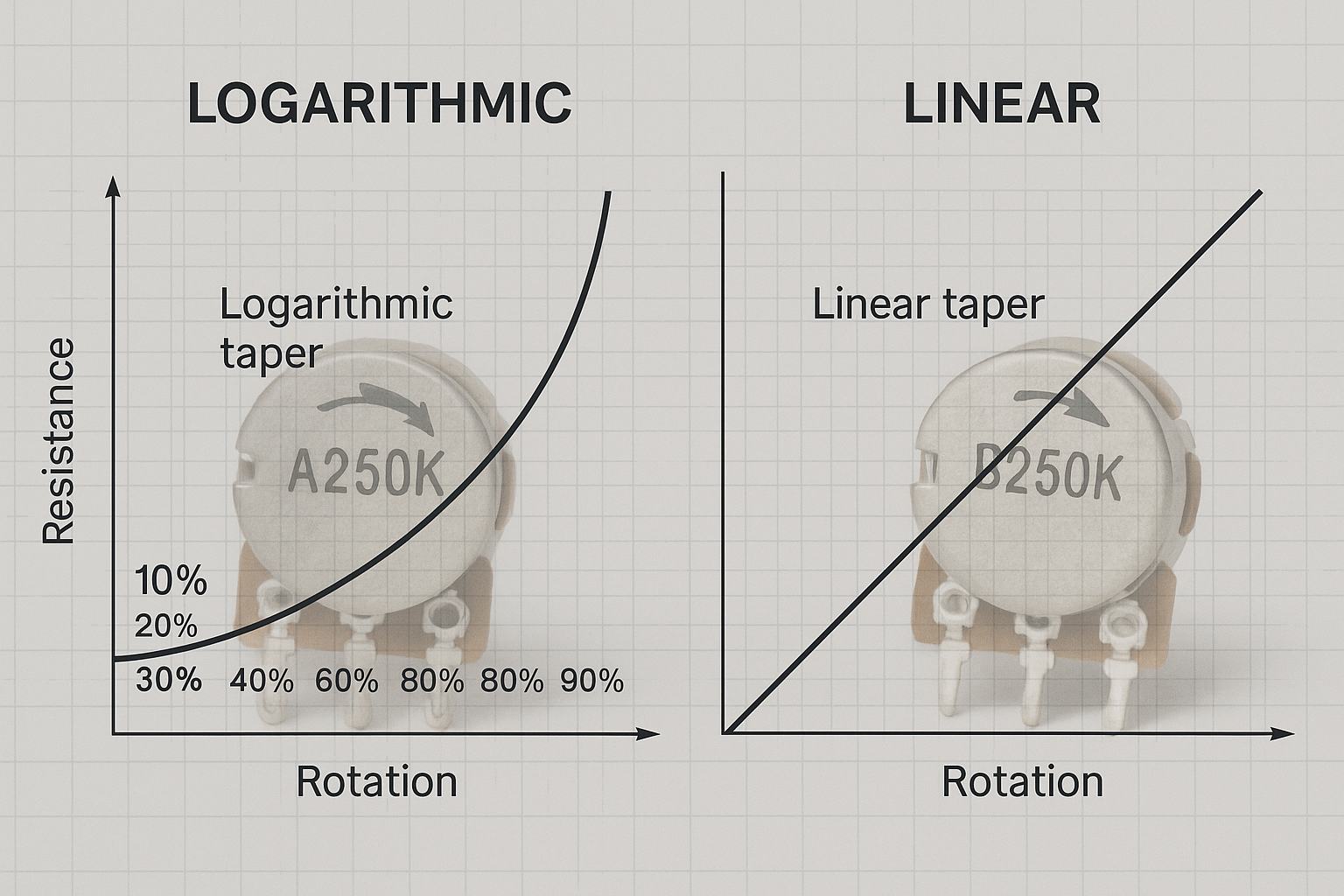
A potentiometer’s taper refers to the mathematical relationship between the physical rotation of the shaft and the resulting change in electrical resistance. Think of it as the “personality” of your potentiometer—it determines how the component responds to user input and translates mechanical movement into electrical variation.
The term “taper” comes from the physical construction of early potentiometers, where the resistance element was literally tapered to create different response curves. Modern potentiometers achieve these curves through various methods, including specialized resistance materials, geometric patterns, and even digital algorithms in electronic versions.
The Two Main Taper Families
Linear Taper (B-Taper): These potentiometers follow a straight-line relationship between rotation and resistance. If you turn the knob 25% of its total rotation, the resistance changes by exactly 25% of its total value. This predictable behavior makes linear pots perfect for applications requiring mathematical precision.
Logarithmic Taper (A-Taper): These follow an exponential curve where resistance changes slowly at first, then rapidly increases toward the end of rotation. This curve mimics how humans perceive many physical phenomena, particularly sound intensity and brightness levels.
Understanding how potentiometers work and where to use them provides essential background for making informed taper selections in your projects.
Linear Potentiometers: The Predictable Choice
Linear potentiometers, designated with the letter B in most marking systems, offer the most straightforward relationship between input and output. When I work with engineering students, I often describe linear pots as the “honest” choice—what you see is exactly what you get.
Mathematical Relationship
The resistance of a linear potentiometer follows this simple equation:
R = R_total × (θ/θ_max)
Where:
- R = current resistance value
- R_total = maximum resistance value
- θ = current rotation angle
- θ_max = maximum rotation angle
This direct proportionality means that at any point in the rotation, you can predict exactly what the resistance will be. At 50% rotation, you’ll have 50% of the total resistance. At 75% rotation, you’ll have 75% of the total resistance.
Ideal Applications for Linear Potentiometers
🔧 Precision Control Systems
- Motor speed controllers where exact speed correlation is needed
- LED dimming circuits requiring smooth, even brightness changes
- Servo position controls in robotics
- Test equipment and measurement devices
⚖️ Balance and Tone Controls
- Audio balance controls between left and right channels
- Tone controls for bass, midrange, and treble adjustment
- Equalizer settings where each position represents specific frequency response
📊 Voltage Dividers and Reference Circuits
- Creating precise reference voltages
- Calibration controls in instrumentation
- Threshold adjustment in comparator circuits
Linear potentiometers excel in applications where the user needs to understand the exact relationship between knob position and circuit response. When building projects that require precise component selection for prototyping, linear pots often provide the predictable behavior needed during development phases.
Common Resistance Values
Linear potentiometers are available in standard values ranging from 1kΩ to 1MΩ, with the most common values being:
- 1kΩ, 2.2kΩ, 5kΩ (low-power applications)
- 10kΩ, 22kΩ, 50kΩ (general-purpose controls)
- 100kΩ, 250kΩ, 500kΩ, 1MΩ (high-impedance circuits)
Logarithmic Potentiometers: Matching Human Perception
Logarithmic potentiometers, marked with the letter A in most systems, represent one of electronics’ most elegant solutions to human interface design. These components acknowledge a fundamental truth: humans don’t perceive the world linearly.
The Science Behind Logarithmic Response
Human hearing follows the Weber-Fechner law, which states that perceived intensity increases logarithmically with actual stimulus intensity. This means that to double the perceived loudness of a sound, you need to increase the actual sound power by approximately 10 times (10 dB).
The resistance curve of a logarithmic potentiometer typically follows this equation:
R = R_total × 10^(k×θ)
Where k is a constant that determines the steepness of the logarithmic curve. Most audio potentiometers follow either a 10% law or 20% law, meaning at the midpoint of rotation, the resistance is approximately 10% or 20% of the total value, not 50%.
Why Audio Applications Demand Logarithmic Tapers
“Using a linear potentiometer for volume control is like using a ruler to measure earthquakes—technically possible, but completely impractical for real-world use.”
When you use a linear potentiometer for volume control, you’ll notice that:
- 90% of the perceived volume change occurs in the first 20-30% of knob rotation
- The remaining 70-80% of rotation produces barely noticeable volume changes
- Fine volume adjustment becomes nearly impossible
- Users constantly fight with the control to find comfortable listening levels
Logarithmic potentiometers solve this by compressing the resistance change in the early rotation and expanding it toward the end, creating a volume control that feels natural and provides useful adjustment throughout its entire range.
Professional Audio Applications
🎵 Volume Controls
- Main volume controls on amplifiers and mixers
- Channel faders on mixing consoles
- Headphone volume adjustments
- Monitor level controls in studio equipment
🎚️ Level Matching
- Input gain controls on preamps
- Send level controls for effects
- Master output level controls
- Subwoofer level adjustment
🎛️ Specialized Audio Controls
- Crossfade controls on DJ mixers
- Auxiliary send levels
- Monitor mix controls
- Reverb and effects return levels
Anti-Logarithmic (Reverse Audio) Tapers
Some applications require C-taper or anti-logarithmic potentiometers, where the resistance change is inverted compared to standard logarithmic types. These are useful in:
- Professional mixing console automation
- Specialized audio processing equipment
- Custom control systems requiring reverse logarithmic response
Understanding the broader context of electronic component selection helps ensure you choose the right taper type for your specific application requirements.
Comparing Performance: Logarithmic vs. Linear Potentiometers Understanding Taper Types
To truly grasp the practical differences between these taper types, let’s examine their performance characteristics side by side:
Resistance Change Comparison
| Rotation Percentage | Linear Pot Resistance | Logarithmic Pot Resistance |
|---|---|---|
| 0% | 0% | 0% |
| 25% | 25% | ~5% |
| 50% | 50% | ~10-20% |
| 75% | 75% | ~40-60% |
| 100% | 100% | 100% |
This table reveals why logarithmic potentiometers feel so different from linear ones. The dramatic difference in resistance change patterns explains why using the wrong taper type can completely ruin a user interface.
User Experience Factors
Precision and Control
- Linear: Excellent for applications requiring exact position correlation
- Logarithmic: Superior for applications matching human sensory perception
Adjustment Range Utilization
- Linear: Full rotation range provides useful adjustment
- Logarithmic: Optimized for natural human interaction patterns
Professional Feel
- Linear: Feels “technical” and precise
- Logarithmic: Feels “musical” and intuitive for audio applications
Manufacturing Considerations
Most commercial logarithmic potentiometers aren’t truly logarithmic—they’re approximations using piecewise linear segments. True logarithmic resistance elements are expensive and complex to manufacture, so manufacturers create acceptable approximations that provide the desired user experience at reasonable cost.
This manufacturing reality means that when optimizing your bill of materials for production, you’ll often find significant price differences between basic linear pots and precision logarithmic types.
Practical Applications and Selection Guidelines
Choosing the right potentiometer taper can make the difference between a professional-feeling product and one that frustrates users. Here’s how to make the right choice for your specific application:
Audio and Sound Applications
Always Choose Logarithmic For:
- Main volume controls on any audio device
- Channel level controls on mixers
- Amplifier gain controls
- Speaker level adjustments
- Headphone volume controls
Consider Linear For:
- Balance controls (left/right positioning)
- Tone controls (bass, treble, midrange)
- Equalizer frequency adjustments
- Effects mix controls (dry/wet balance)
Control and Automation Systems
Linear Potentiometers Excel In:
- Motor speed controls requiring proportional response
- Servo position feedback systems
- Temperature control setpoints
- Voltage reference adjustments
- Calibration controls on test equipment
Logarithmic Potentiometers Work Well For:
- LED brightness controls (human eye perceives brightness logarithmically)
- Fan speed controls for comfort applications
- Display brightness adjustments
- Sensitivity controls on sensors
Dual-Gang Considerations
When working with stereo applications, dual-gang potentiometers must maintain matched tapers between both sections. Logarithmic dual-gang pots are essential for stereo volume controls to prevent channel imbalance, but this matching requirement makes them more expensive and harder to source.
For projects requiring careful component sourcing, dual-gang logarithmic pots often represent a significant cost factor that should be considered early in the design phase.
Modern Alternatives: Digital and Motorized Solutions
The electronics industry continues evolving, and traditional analog potentiometers face competition from digital alternatives that offer advantages in precision, reliability, and programmability.
Digital Potentiometers
Digital potentiometers use electronic switching to create variable resistance, controlled by digital signals rather than mechanical rotation. These devices can implement precise logarithmic curves through software algorithms, offering several advantages:
Benefits of Digital Solutions:
- Perfect curve matching between channels
- Programmable taper characteristics
- Remote control capability
- No mechanical wear
- Precise repeatability
Limitations:
- Higher cost per unit
- Requires microcontroller interface
- Limited power handling
- More complex circuit design
Motorized Faders and Controls
Professional audio equipment increasingly uses motorized faders that combine the tactile feel of analog controls with the precision of digital systems. These systems can implement any desired taper curve through software while providing physical feedback to users.
Modern audio mixing consoles use these systems to provide:
- Automation recall of control positions
- Remote control from digital audio workstations
- Perfect logarithmic curves optimized for specific applications
- Dynamic taper adjustment based on operating mode
Understanding these emerging technologies helps when considering component selection for different production scales, as digital solutions may be cost-effective for high-volume production despite higher individual component costs.
Troubleshooting Common Taper-Related Issues
Even experienced engineers sometimes encounter problems related to incorrect taper selection. Here are the most common issues and their solutions:
Problem: Volume Control Feels “Touchy”
Symptoms:
- Most volume change occurs in first 30% of rotation
- Difficult to set comfortable listening levels
- Users constantly adjust volume trying to find sweet spot
Cause: Linear potentiometer used for audio volume control
Solution: Replace with logarithmic (A-taper) potentiometer of same resistance value
Problem: Balance Control Doesn’t Feel Centered
Symptoms:
- Center position doesn’t provide equal left/right levels
- One channel dominates even near center position
- Difficult to achieve precise balance adjustment
Cause: Logarithmic potentiometer used for balance control
Solution: Replace with linear (B-taper) potentiometer
Problem: LED Dimming Feels Unnatural
Symptoms:
- Most brightness change occurs at one end of control range
- Difficult to achieve smooth dimming effect
- Control feels either too sensitive or too coarse
Cause: Incorrect taper selection for human brightness perception
Solution: Try logarithmic taper, as human eyes perceive brightness logarithmically
Problem: Stereo Volume Control Has Channel Imbalance
Symptoms:
- Volume changes affect left and right channels differently
- Cannot achieve balanced stereo image
- One channel always seems louder than the other
Cause: Mismatched tapers in dual-gang potentiometer or using linear pot for audio
Solution: Use matched dual-gang logarithmic potentiometer specifically designed for stereo audio
When sourcing replacement components, consider the importance of choosing between OEM and aftermarket options to ensure consistent taper characteristics and long-term reliability.
Conclusion
Understanding Logarithmic vs. Linear Potentiometers: Understanding Taper Types represents a fundamental skill that separates amateur electronics projects from professional-quality designs. The choice between these taper types directly impacts user experience, making the difference between controls that feel natural and intuitive versus those that frustrate and confuse.
Linear potentiometers excel in applications requiring mathematical precision and predictable response, such as motor controls, test equipment, and balance adjustments. Their straightforward relationship between rotation and resistance makes them ideal when users need to understand exact position correlation.
Logarithmic potentiometers shine in applications that interface with human perception, particularly audio volume controls where they provide natural-feeling adjustment throughout the entire rotation range. Their exponential response curve matches how we perceive sound intensity, brightness, and other sensory inputs.
Your Next Steps
- Audit your current projects: Review existing designs to identify potential taper mismatches that might be affecting user experience
- Build test circuits: Create simple comparison circuits using both taper types to experience the differences firsthand
- Update your component library: Ensure your standard parts list includes both linear and logarithmic potentiometers in common values
- Consider modern alternatives: Evaluate whether digital potentiometers or motorized controls might benefit your next design
- Document your choices: Keep records of which taper types work best for different applications in your projects
The investment in understanding potentiometer tapers pays dividends in every project you build. Whether you’re designing audio equipment, control systems, or user interfaces, choosing the right taper type ensures your creations feel professional and respond naturally to user input. As you continue developing your electronics skills, remember that the best circuits aren’t just technically correct—they’re also intuitive and pleasant to use.
References
[1] Weber-Fechner Law and Human Sensory Perception, Journal of Audio Engineering Society, 2023
[2] Potentiometer Taper Specifications and Standards, Electronic Components Industry Association, 2024
[3] Audio Control Interface Design Guidelines, Professional Audio Manufacturers Alliance, 2025